Controlling DC Motors Using Python With a Raspberry Pi
In this tutorial I will show you how to connect some motors
to your Raspberry Pi. Doing so will allow your Raspberry Pi to interact in the
real world, making it possible to build a robot, turn on a fan on a hot day or
even drop a treat for your cat or dog while your away.
Objective
What we plan to do is safely connect one or two motors to
the Raspberry Pi with as few components as possible. Once we have the
electronics put together on the breadboard, I will show you how to control them
easily using Python to first make the motor spin, and then add some control to
change the motor direction so we can go backwards.
This guide will require a careful eye to catch any mistakes,
and a bit of courage, especially if you are new to the GPIO connectors. I would
like to stress I am not responsible for any damage caused to your Raspberry Pi
and/or components.
IMPORTANT: Do not
connect a motor, no matter how small
directly to the Raspberry Pi, it will damage your Raspberry Pi.
The main
processor can only supply enough power to light a LED, roughly 20mA. A motor
will want at least 400mA of current to start turning.
Requirements
To get a motor running, you will need:
A Raspberry Pi with SD card preinstalled with
Raspbian
A Breadboard to connect everything on
An L293 or SN755410 motor driver chip (I will
refer both as L293D in this tutorial)
Jumper cables to connect everything up (Male to
male and female to male)
One or two DC motors rated for 6v
4x AA batteries and holder
GPIO pins
If you haven’t looked
closely at your Raspberry Pi before, now might be the best time to have a good
look. There are 26 pins grouped in two rows of 13, and these collectively are
called the General Purpose Input Output header or GPIO for short. These are a
mix of four power pins, five ground pins and 17 data pins.
Figure 1. The Layout of the GPIOs with the pin numbering. Pin 1 is the top left labelled 3V3
Some of these data pins have extra functions such as an i2c
bus, SPI bus and UART serial connectors, all of which can connect to other
hardware to allow the Raspberry Pi to talk to items such as an Arduino, an
Analogue to Digital Convertor (ADC) or add-on boards such as a PiGlow or
PiFace. TIP:When working
with the GPIO pins, always do this while the Pi is unplugged, as any accident
by connecting (or shorting) 2 pins together can cause damage to the Raspberry
Pi.
Assembling the Circuit
Adding Power and Ground
It is important to do this while the power to the
Raspberry Pi is off, or disconnected, as you want to avoid shorting any connectors by mistake.
The first thing you need to do is connect up the
power and ground wires. As with most electronics projects, everything that
connects together will require a common ground. This is shown with the black
wires.
Figure 2: Connect the power and ground wiresThe ground on the Raspberry Pi is physical pin 6. Referring
to Figure one this is worked out by starting at the top left with pin 3V3,
counting left to right so 5V is pin 2, GPIO 2 (labelled 2) is pin 3 and so
on.
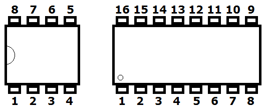
Reading pin numbers on Integrated Circuit (IC) chips is
easily done by having the notch or dot to the left then starting from bottom
left gives us pin 1.
Figure 3. Pin 1 is at the bottom left
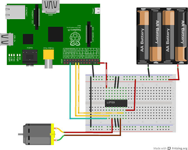
Adding the Data Wires
Now add three wires from the GPIO pins to the L293D.
GPIO 25–Pin 22 > L293D–Pin 1
GPIO 24–Pin 18 > L293D–Pin 2
GPIO 23–Pin 16 > L293D–Pin 7
Figure 4. Add the three GPIO wires to control the motor
Add the motor:
Motor–wire 1 > L293D–pin 3
Motor–wire 2 > L293D–pin 6
Figure 5. Attached the battery and the motor
It is extremely important that you double-check every connection before adding
the batteries. Only when you are happy that everything is in place, connect the
battery wires to the power rails of the breadboard.
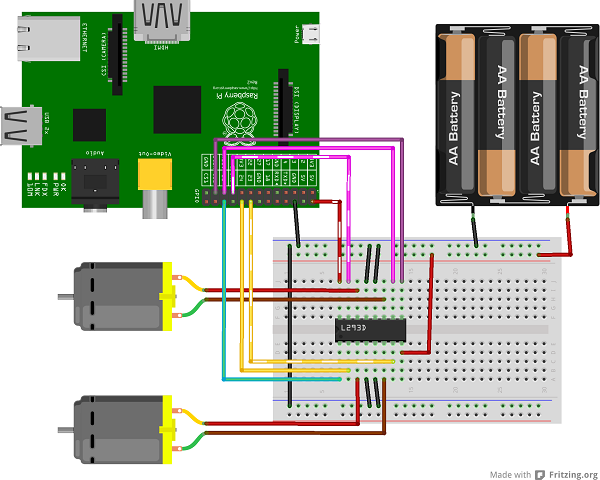
Add a Second Motor (Optional)
One of the great
features of the L293D is it that it can handle two motors independently and each motor can run at different speeds or directions. Using this one IC
makes it possible to create a two-wheeled robot capable of turning, going
forwards and going backwards easily.
Adding a second motor involves just three additional wires and
another motor.
GPIO 11–Pin 23 > L293D–Pin 9
GPIO 9–Pin 21 > L293D–Pin 10
GPIO 10–Pin 19 > L293D–Pin 15
The complete set up ready for robotics
Powering On
It is important to check and double-check any wiring before
adding any power source to your project as some of the wiring can get a bit
fiddly it is easy to miss a connection and send 5V in to the 3.3V of the
Raspberry Pi.
Always check your wiring and then check it again!
If you haven’t set up an SD card for your Pi before, it will be worth understanding how to create one by reading the How to Flash an SD Card for Raspberry Pi tutorial, first.
With a freshly created Raspbian SD card in place connect the Raspberry Pi as usual and boot up.
Add the batteries, ensuring that you pay attention to
the correct rails (the long strips along the top and bottom, if you have any),
as you only want the black wire to connect to the ground, and the red wire to
positive or source of the chip only.
The next job is to tell the Raspberry Pi that a motor, or two, has been connected. To do this I am using a language called Python.
It comes installed on Raspbian which is a bonus. If you are
using another Operating System such as Arch or PiDora, double-check if RPi.GPIO
is available.
Testing
In order to get the motors to work double-click
LXTerminal on your desktop to bring up a terminal window. This is where you will be writing Python code using a program
called Nano. Nano is a text editor, similar to Notepad or TextEdit but for the command prompt, I will
teach your some commands as we go along if you are new to it.
To turn the motor on for two seconds use the following code:
01
02
03
04
05
06
07
08
09
10
11
12
13
14
15
16
17
18
19
20
21
22
23
24
importRPi.GPIO as GPIO
fromtime importsleep
GPIO.setmode(GPIO.BOARD)
Motor1A =16
Motor1B =18
Motor1E =22
GPIO.setup(Motor1A,GPIO.OUT)
GPIO.setup(Motor1B,GPIO.OUT)
GPIO.setup(Motor1E,GPIO.OUT)
print"Turning motor on"
GPIO.output(Motor1A,GPIO.HIGH)
GPIO.output(Motor1B,GPIO.LOW)
GPIO.output(Motor1E,GPIO.HIGH)
sleep(2)
print"Stopping motor"
GPIO.output(Motor1E,GPIO.LOW)
GPIO.cleanup()
The first two lines tell Python what is needed in the program.
The first line will want to access a module called RPi.GPIO. This module handles all the
hard work involved around turning the GPIO pins on and off on the Raspberry Pi.
The second line brings in sleep from
the module time to make it possible
to pause the script giving it time to
perform a certain action, in this case leaving a motor on for a few seconds.
The function setmode tells RPi.GPIO to use the board numbering on the Raspberry Pi. The numbers 16, 18 and 22 we will use to tell
Python they are the pins associated with the motors.
When using the
L293D you can give it a direction, by turning one side on to turn in
one direction, called pin A and vice versa is pin B. To turn the motor on use a pin called Enable, labelled E in the test script–this is pin 22. I'll cover this a bit more later.
Finally, tell the Raspberry Pi these are
all outputs which is done with GPIO.OUT.
With the script set up, the Raspberry Pi ready to turn the
motors. It will turn on some pins, wait two seconds then turn them
off again, shown in the remainder of the script.
Save and exit by pressing CTRL-X, along the bottom a message asks you to confirm the
changes. Press Y and Enter to confirm. Now you are back at
the command prompt to run the script and see the motor spin to life. sudo
python motor.py
If the motor didn’t turn, double check your wiring or
batteries. Debugging and finding out why something doesn’t work can be
annoying, but is a useful step in learning something new!
Advertisement
Now Go Backwards
It’s brilliant to have a motor spin, but even
better to make it turn backwards, so I'll show you how to do that.
Nothing needs to be done to the wiring, this is purely
Python now. This is achieved by creating a new script, calling it motorback.py. To create the script in Nano, enter the command: nano
motorback.py
Enter the following code:
01
02
03
04
05
06
07
08
09
10
11
12
13
14
15
16
17
18
19
20
21
22
23
24
25
26
27
28
29
30
31
importRPi.GPIO as GPIO
fromtime importsleep
GPIO.setmode(GPIO.BOARD)
Motor1A =16
Motor1B =18
Motor1E =22
GPIO.setup(Motor1A,GPIO.OUT)
GPIO.setup(Motor1B,GPIO.OUT)
GPIO.setup(Motor1E,GPIO.OUT)
print"Going forwards"
GPIO.output(Motor1A,GPIO.HIGH)
GPIO.output(Motor1B,GPIO.LOW)
GPIO.output(Motor1E,GPIO.HIGH)
sleep(2)
print"Going backwards"
GPIO.output(Motor1A,GPIO.LOW)
GPIO.output(Motor1B,GPIO.HIGH)
GPIO.output(Motor1E,GPIO.HIGH)
sleep(2)
print"Now stop"
GPIO.output(Motor1E,GPIO.LOW)
GPIO.cleanup()
CTRL-X then Y followed by Enter to save.
The script is very
similar to the previous one, but if you notice for backwards we made Motor1Alow and Motor1Bhigh. High and low are programming names for on
and off.
To stop the motor you'll turn
off, low, Motor1E. Enable is the switch to turn the motor on and off, regardless of what A and B are doing.
If you are finding this confusing, look at a Truth Table
to see what is happening.
Truth table
There are only two states
which allow the motor to turn, when Enable is on or high, and either AorB must be high, but not both.
For two motors look at the following script. All
that is different is a couple more lines to set up the second motor.
01
02
03
04
05
06
07
08
09
10
11
12
13
14
15
16
17
18
19
20
21
22
23
24
25
26
27
28
29
30
31
32
33
34
35
36
37
38
39
40
41
42
43
44
45
46
47
48
importRPi.GPIO as GPIO
fromtime importsleep
GPIO.setmode(GPIO.BOARD)
Motor1A =16
Motor1B =18
Motor1E =22
Motor2A =23
Motor2B =21
Motor2E =19
GPIO.setup(Motor1A,GPIO.OUT)
GPIO.setup(Motor1B,GPIO.OUT)
GPIO.setup(Motor1E,GPIO.OUT)
GPIO.setup(Motor2A,GPIO.OUT)
GPIO.setup(Motor2B,GPIO.OUT)
GPIO.setup(Motor2E,GPIO.OUT)
print"Going forwards"
GPIO.output(Motor1A,GPIO.HIGH)
GPIO.output(Motor1B,GPIO.LOW)
GPIO.output(Motor1E,GPIO.HIGH)
GPIO.output(Motor2A,GPIO.HIGH)
GPIO.output(Motor2B,GPIO.LOW)
GPIO.output(Motor2E,GPIO.HIGH)
sleep(2)
print"Going backwards"
GPIO.output(Motor1A,GPIO.LOW)
GPIO.output(Motor1B,GPIO.HIGH)
GPIO.output(Motor1E,GPIO.HIGH)
GPIO.output(Motor2A,GPIO.LOW)
GPIO.output(Motor2B,GPIO.HIGH)
GPIO.output(Motor2E,GPIO.HIGH)
sleep(2)
print"Now stop"
GPIO.output(Motor1E,GPIO.LOW)
GPIO.output(Motor2E,GPIO.LOW)
GPIO.cleanup()
Conclusion
In this tutorial I have shown you the basics of connecting motors to your Raspberry Pi. It may take a deep breath and
can-do it attitude if you are new to connecting anything to your brand new Pi,
but you will soon find that once you start playing with the GPIO pins
that it is hard to stop.
This tutorial opens the doors to making anything like robots
with blinking LED lights and ultrasonic sensors in order to sense its environment.
Find a chassis to mount everything on use a USB mobile phone charger battery to make your Raspberry Pi fully mobile.


No comments:
Post a Comment